sabato 18 febbraio 2023

Disassembly HP Pavilion DV8 display components and frame (spare part 496876-001, DD0UT7LC002)

Supplementing insidemylaptop's excellent guide on disassembling the HP DV8 Pavilion, in the following wizard I will show how to disassemble the display components to replace the internal video cable. The tutorial can also be used to replace the other components (webcam-microphone, inverter, wireless antenna).

This wizard assumes that you arrived at STEP 21 (taking apart the display from the rest of the notebook) of the insidemylaptop tutorial and will be supported by photos and screenshots from HP's official Service Manual. You can click on the figures to enlarge them.

pic.1

Of all the components visible in picture 1 I will replace the 2c video cable because after many years it causes screen flickering and shutdown due to internal injury of the cable near the screen joint (the screen turns on and off by squeezing the cable).

Components for these dated PCs are rare by now and in my case I managed to find it on ebay paying about 36 euros and importing it from the UK. In pic.2 the video cable for the HP Pavilion DV8 1010el (1000 series).

 pic.2

1. After STEP 21 of the insidemylaptop tutorial the display will look like this:

pic.3

 
2. Remove the stickers indicated with number 1 in picture 4 and unscrew the 4 screws
 
pic.4
 
pic.5
3. Turn the display upside down (pic.5) and with the help of the removal kits such as paddles and pick-ups unhook the plastic backcover from the display frame (pic.6) being careful not to bend the plastic too much before unhooking the cover all around the display frame
pic.6
pic.7
pic.8
4. When the backcover is completely unfastened move it slightly (pic.8) to reveal the wire that goes to power the HP back LED before taking apart the backcover from the display frame.
pic.9
pic.10
5. The wire to be disconnected is number 3 in picture 9. In this specific case I found the wire under the hinge cover so I proceeded to disassemble it by unscrewing the 4 screws in picture 10. Once the flap was removed, gently disconnect the wire visible in pic.11 (before being disconnected) and pic.12 (after being disconnected)
pic.11
pic.12
6. Now you can take apart the backcover from the display (pic.13)
pic.13
pic.14
 7. The back part of the display will look like in picture 14. The cable video is shown in pic.15
pic.15
8. Peel off the sticker (n.1 pic.16) that keeps the top of the wiring secured to not be disconnected with shocks.
Once the sticker is lifted, disconnect the yellow-colored wiring. Highlighted with the number 1 in pic.17.
Next, disconnect the wiring number 2 from pic.17 (or n. 3 in pic.16) that connects the display to the inverter. Disconnect the cable by applying light pressure to the plastic first from the right side and then from the left side until it can be disconnected. Do not use too much force or you may damage the inverter port.
pic. 16
 pic. 17
9. Replace the video cable with the new one and reconnect wiring 1 and 2 visible from pic.17. Completed this operation, move the cables near the display joint, according to pic.18, before closing the flap removed in step 5 of this tutorial.
pic.18
 
9-bis. If you need to replace the webcam you can proceed now, before closing the hinge cover.
Unscrew the screw number 1 (pic.19), lift the webcam out of the housing and disconnect the wiring (visible in pic.20), helping yourself with a screwdriver by loosening it slightly to the right and then to the left until it is free to come out. Caution: do not pull directly the cable or you may damage it.
Replace the webcam and its cable with the new ones.
pic.19
 
pic.20
  
10. You can now proceed with the reassembly of the display by following in reverse steps number 1 through 6 of this wizard. Do not forget to reconnect the HP back LED before re-attaching the backcover to the display frame (step 5).
Picture 21 shows the final result.
pic.21


Insight:
In pic.22 you can check the compatibility of the cable with spare part number 496876-001 according to the HP Service Manual. In my case I purchased a cable code DD0UT7LC002 (which you can see in the third column) and I had perfect compatibility with my old cable.
The source of the compatibility chart is the battery-adapter website. I specify that I purchased the cable on ebay and not on this website.
pic.22


This article is property of PC Wizard wroted by Michele Campofredano (Italy). Please don't copy and paste without mentioning the blog and the author.
or use the QR code:
QR code 


Sostituzione cavo video interno del notebook HP Pavilion DV8 (spare part 496876-001, DD0UT7LC002)


Integrando l'ottima guida sullo smontaggio dell'HP DV8 Pavilion di insidemylaptop, nel seguito verrà mostrato come smontare i componenti del display per sostituire il cavo video interno in seguito all'usura dello stesso. La guida può essere utilizzata anche per sostituire gli altri componenti (webcam-microfono, inverter, antenna wireless). 

La guida presuppone che si sia arrivati allo STEP 21 (separazione del display dal resto del notebook) del tutorial di insidemylaptop e sarà supportata da foto e screenshot del Service Manual ufficiale di HP. Potete cliccare sulle figure per ingrandirle.

fig.1

Tra i componenti visibili nell'immagine sarà sostituito il cavo video 2c perché dopo molti anni provoca sfarfallamento dello schermo e spegnimento dovuto a lesioni interne al cavo nei pressi dello snodo dello schermo (lo schermo si accende e si spegne schiacciando il cavo).

I componenti per questi pc ormai datati sono praticamente introvabili e nel mio caso sono riuscito a trovarlo su ebay pagandolo circa 36 euro e importandolo dal Regno Unito. In fig.2 il cavo video per l'HP Pavilion DV8 1010el (serie 1000).

 fig.2

1. Dopo lo STEP 21 del tutorial di insidemylaptop il display si presenterà così:

fig.3

 
2. Rimuoviamo gli adesivi indicati con il numero 1 nella figura 4 e svitiamo le 4 viti
 
fig.4
 
fig.5

3. Capovolgiamo il display (fig.5) e con l'ausilio dei kit di rimozione quali palette e pick-up sganciamo la back cover in plastica dalla cornice del display (fig.6) facendo attenzione a non piegare troppo la plastica prima di aver sganciato la cover tutta intorno alla cornice del display
fig.6
fig.7
fig.8
4. Quando la back cover sarà completamente sganciata spostatela leggermente (fig.8) per scoprire il cavetto che va ad alimentare il led posteriore HP prima di poter separare la backcover dalla cornice del display.
fig.9
fig.10
5. Il cavetto da scollegare è il numero 3 della figura 9. Nel caso specifico ho trovato il cavetto sotto il coperchio della cerniera quindi ho provveduto a smontarla svitando le 4 viti della figura 10. Una volta tolto lo sportellino scollegare delicatamente il cavetto visibile nella fig.11 (prima di essere scollegato) e nella fig.12 (dopo essere stato scollegato)
fig.11
fig.12
6. Adesso potete separare la backcover dal display (fig.13)
fig.13
fig.14
 7. La parte posteriore del display si presenterà come visibile in figura 14. Il cavo video è mostrato in fig.15.
fig.15
8. Stacchiamo l'adesivo (n.1 fig.16) che mantiene la parte alta del cablaggio fissata per non scollegarsi con gli urti.
Una volta sollevato l'adesivo scolleghiamo il cablaggio di colore giallo. Evidenziato con il numero 1 nella fig.17.
Successivamente scolleghiamo anche il cablaggio numero 2 di fig.17 (oppure n. 3 di fig.16) che connette il display all'inverter. Scollegare il cavo esercitando una lieve pressione sulla plastica prima dal lato destro e poi dal sinistro fino a quando non si sarà allentato e potrà essere scollegato. Non usare troppa forza o si rischia di danneggiare la porta dell'inverter
fig. 16
 fig. 17
9. Sostituiamo il cavo video con il nuovo e ricolleghiamo i cablaggi 1 e 2 della fig.17. Completata questa operazione facciamo passare i cavi vicino allo snodo del display, secondo quando mostrato dalla figura 18, prima di richiudere lo sportellino rimosso allo step 5 di questa guida.
fig.18
 
9-bis. Qualora aveste bisogno di sostituire la webcam potete procedere ora, prima della chiusura del coperchio della cerniera. 
Svitare la vite numero 1 (fig.19), sollevare la webcam dall'allogiamento e scollegare il cablaggio (visibile in fig.20) aiutandosi con un cacciavite allentandolo leggermente a destra e poi a sinistra fino a quando sarà libero di uscire. Attenzione: non tirare il cavo per estrarlo o potreste danneggiarlo.
Sostituite la webcam e il relativo cavo con i nuovi.
fig.19
 
fig.20
  
10. Potete adesso procedere con il riassemblaggio del display ripercorrendo a ritroso i passaggi dal numero 1 al 6 di questa guida. Non dimenticate di ricollegare il led posteriore HP prima di riagganciare il coperchio posteriore alla cornice del display (step 5).
In fig.21 il risultato finale.
fig.21


Approfondimento:
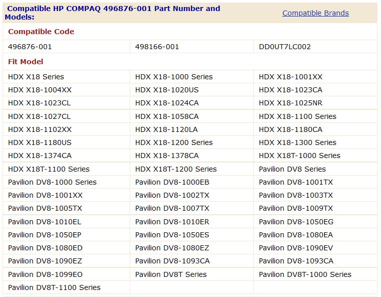
In fig.22 potete controllare le compatibilità del cavo con codice ricambio 496876-001 secondo il Service Manual HP. Nel mio caso ho acquistato un cavo codice DD0UT7LC002 (che potete vedere nella terza colonna) ed ho avuto una perfetta compatibilità con il mio vecchio cavo.
La sorgente della tabella di compatibilità è il sito battery-adapter. Specifico che ho acquistato il cavo su ebay quindi non su questo sito.
fig.22


This article is property of PC Wizard wroted by Michele Campofredano (Italy). Please don't copy and paste without mentioning the blog and the author.
or use the QR code:
QR code